
Introduction
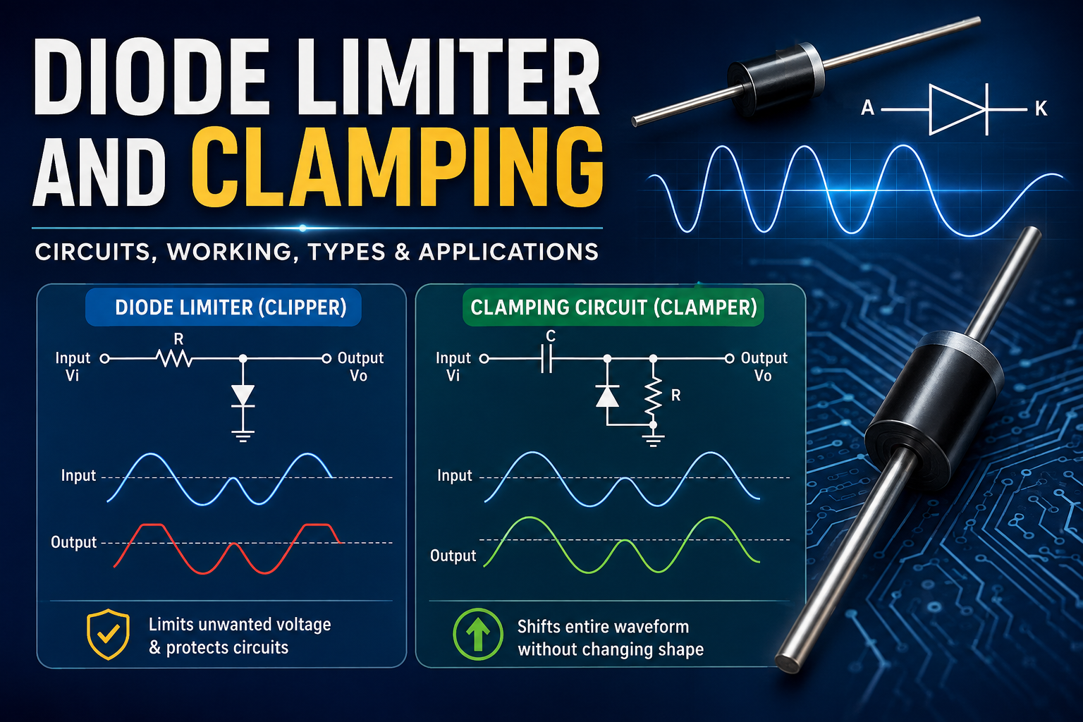
A diode limiter and clamping circuit is one of the most important concepts in electronics. These circuits are widely used in communication systems, signal processing, power supplies, and digital electronics to control voltage levels and protect sensitive electronic components. Whether you are an engineering student, electronics hobbyist, or professional technician, understanding diode limiter and clamping circuits can help you design safer and more efficient electronic systems.
Diodes are semiconductor devices that allow current to flow in one direction while blocking it in the opposite direction. By arranging diodes with resistors, capacitors, and voltage sources, engineers can create circuits that either limit unwanted voltage peaks or shift an entire waveform without changing its original shape.
This article explains diode limiter and clamping circuits in detail, including their working principles, types, applications, advantages, disadvantages, and the differences between them.
What Is a Diode Limiter?
A diode limiter, also known as a clipper circuit, is an electronic circuit that removes or clips a portion of an input signal once it exceeds a predetermined voltage level.
Instead of allowing the entire waveform to pass through, the limiter blocks the voltage that goes beyond the selected limit. The remaining portion of the waveform continues unaffected.
The primary purpose of a diode limiter is to protect electronic circuits from excessive voltage while maintaining the useful part of the signal.
Working Principle of a Diode Limiter
The operation of a diode limiter depends on the diode’s forward and reverse bias characteristics.
When the input voltage is below the clipping level:
- The diode remains reverse biased.
- The input signal appears at the output.
When the voltage exceeds the clipping point:
- The diode becomes forward biased.
- It conducts current.
- Excess voltage is diverted away.
- The output voltage remains fixed at the clipping level.
This simple operation makes limiter circuits extremely useful for voltage protection.
Types of Diode Limiter Circuits
There are several types of diode limiter circuits.
1. Positive Limiter
A positive limiter clips the positive half of the input waveform while allowing the negative portion to pass.
Applications include:
- Over-voltage protection
- Communication receivers
- Signal conditioning
2. Negative Limiter
A negative limiter clips the negative half-cycle while allowing positive voltages to pass normally.
It is commonly used in:
- Pulse circuits
- Digital electronics
- Audio systems
3. Biased Limiter
A biased limiter uses an additional DC voltage source to set the clipping level at a desired voltage rather than at the diode’s forward voltage.
Advantages include:
- Adjustable clipping voltage
- Greater flexibility
- Improved signal control
4. Dual Limiter
A dual limiter clips both positive and negative portions of the waveform.
This type is ideal for:
- Signal shaping
- Waveform conditioning
- Voltage protection
Applications of Diode Limiter
Diode limiter circuits are found in many electronic systems.
Common applications include:
- Voltage protection
- Communication equipment
- Television circuits
- Oscilloscopes
- Medical electronics
- Audio amplifiers
- Digital logic systems
- Radar equipment
- Power electronics
- Embedded systems
Advantages of Diode Limiter
Some major advantages include:
- Simple circuit design
- Low cost
- Reliable operation
- Fast response time
- Excellent over-voltage protection
- Low power consumption
- High efficiency
Disadvantages of Diode Limiter
Despite their benefits, limiter circuits also have some drawbacks.
These include:
- Signal distortion
- Limited voltage control without biasing
- Not suitable for high-power applications
- Temperature dependence of diode characteristics
What Is a Clamping Circuit?
A clamping circuit, also called a clamper, is an electronic circuit that shifts the entire voltage level of an AC waveform upward or downward without changing its overall shape.
Unlike a limiter, which removes part of the waveform, a clamper preserves the waveform while changing its DC reference level.
A clamping circuit usually consists of:
- Diode
- Capacitor
- Resistor
Sometimes an external voltage source is also added.
Working Principle of a Clamping Circuit
The capacitor plays the most important role in a clamping circuit.
During one half-cycle:
- The diode conducts.
- The capacitor charges.
During the opposite half-cycle:
- The diode becomes reverse biased.
- The capacitor acts like a voltage source.
- The stored charge shifts the entire waveform.
As a result, the waveform moves upward or downward without changing its amplitude.
Types of Clamping Circuits
Positive Clamper
A positive clamper shifts the entire waveform upward.
The negative peaks move closer to zero while the positive peaks increase by the same amount.
Applications include:
- Television receivers
- Signal restoration
- Analog circuits
Negative Clamper
A negative clamper shifts the waveform downward.
The positive peaks move toward zero while the negative peaks become more negative.
It is commonly used in:
- Signal processing
- Communication systems
- Display electronics
Biased Clamper
A biased clamper uses an external voltage source to shift the waveform by a predetermined amount.
This provides greater control over the output voltage.
Components Used in Clamping Circuits
A basic clamping circuit requires only a few components.
Diode
Controls the charging and discharging path.
Capacitor
Stores electrical energy and shifts the waveform.
Resistor
Provides the discharge path and determines the time constant.
DC Source (Optional)
Creates a biased clamping level.
Applications of Clamping Circuits
Clamping circuits are widely used in modern electronics.
Major applications include:
- Television receivers
- Oscilloscopes
- Voltage restoration
- Signal processing
- Communication transmitters
- Digital electronics
- Pulse circuits
- Audio equipment
- Medical instruments
- Electronic testing equipment
Advantages of Clamping Circuits
Benefits include:
- Maintains waveform shape
- Easy circuit construction
- Low manufacturing cost
- Reliable operation
- Improves signal quality
- Efficient DC restoration
- Low component count
Disadvantages of Clamping Circuits
Some limitations include:
- Requires capacitor charging time
- Performance depends on component values
- Frequency-sensitive operation
- Capacitor leakage can affect accuracy
Difference Between Diode Limiter and Clamping Circuit
| Feature | Diode Limiter | Clamping Circuit |
|---|---|---|
| Main Purpose | Clips voltage | Shifts voltage level |
| Waveform Shape | Partially removed | Fully preserved |
| Main Components | Diode and resistor | Diode, capacitor, resistor |
| Signal Amplitude | Reduced | Remains unchanged |
| DC Level | Usually unchanged | Shifted upward or downward |
| Primary Use | Protection | DC restoration |
Practical Example
Suppose an input signal varies from +10V to -10V.
Using a Limiter
A positive limiter set at +5V clips all voltages above +5V.
Output:
- Positive maximum = +5V
- Negative maximum = -10V
Using a Clamper
A positive clamper shifts the waveform upward by 10V.
Output becomes:
- Maximum = +20V
- Minimum = 0V
Notice that the waveform shape remains identical.
Importance in Modern Electronics
Diode limiter and clamping circuits play a critical role in today’s electronic devices.
They help protect expensive integrated circuits from voltage spikes, improve communication signal quality, stabilize digital signals, and ensure reliable operation of electronic equipment.
Modern applications include:
- Smartphones
- Computers
- Industrial automation
- Automotive electronics
- Renewable energy systems
- Medical equipment
- Consumer electronics
- Internet of Things (IoT) devices
- Embedded systems
- Wireless communication networks
Without these circuits, many sensitive semiconductor devices would be vulnerable to electrical damage and signal distortion.
Tips for Designing Diode Limiter and Clamping Circuits
To achieve the best performance:
- Select diodes with appropriate forward voltage and switching speed.
- Use capacitors with low leakage for clamping circuits.
- Choose resistor values that provide the desired charging and discharging time constants.
- Account for temperature effects on diode behavior.
- Simulate the circuit before building it to verify clipping or clamping levels.
Proper component selection ensures accurate waveform control and reliable long-term operation.
Future Trends
As electronic systems become faster and more compact, diode limiter and clamping circuits continue to evolve. Modern designs increasingly use Schottky diodes, Zener diodes, and integrated protection devices to provide faster switching, lower voltage drops, and enhanced protection for high-speed digital and communication circuits. These improvements are especially important in 5G networks, IoT devices, electric vehicles, and advanced computing systems.
Conclusion
Understanding diode limiter and clamping circuits is essential for anyone studying or working with electronics. Although both circuits use diodes, they serve different purposes. A diode limiter protects circuits by clipping unwanted voltage levels, while a clamping circuit shifts the entire waveform to a new DC reference without altering its shape.
Together, these circuits are fundamental building blocks in analog and digital electronics, helping improve signal quality, protect sensitive components, and ensure reliable system performance. By learning how they work, their types, and their applications, you can confidently apply diode limiter and clamping circuits in a wide range of electronic designs.